Posts

Ideal vs real Gases 4

Image
  Equation of State for the Real Gases (van der Waals Equation) To explain the behaviour of real gases, J .D. van der Waals, in 1873, modified the ideal gas equation applying appropriate corrections so as to take into account The volume of the gas molecules The forces of attraction between the gas molecules He put forward the modified equation, known after him as van der Waals equation. The equation is For 1 mole of the gas, For n moles of the gas, Where ‘a’ and ‘b’ van der Waals constant.There values depend upon nature of gas. Significance of Van der Waals Constants Van der Waals constant ‘a’:  Its value is a measure of the magnitude of the attractive forces among the molecules of the gas. There would be large intermolecular forces of attraction if the value ‘a’, is large. Van der Waals constant ‘b’:  Its value is a measure of the effective size of the gas molecules. Its value is equal to four times the actual volume of the gas molecules. It is called  Excluded Volume  or  Co-volume .

Real vs Ideal gases 3

Image
  Significance of compressibility factor The significance of compressibility factor can be further understood from the following derivation: If the gas shows ideal behaviour, Substituting this value of nRT/P in eqn. (1), we get Thus, compressibility factor is defined as the ratio of the actual molar volume of the gas ( For Example:  experimentally observed value) to the calculated molar volume (considering it as an ideal gas) at the same temperature and pressure. Causes of Deviation from Ideal Behaviour As stated above, the real gases obey ideal gas equation (PV = nRT) only if the pressure is low the temperature is high. However, if the pressure is high or the temperature is low, the real gases show marked deviations from ideal behaviour. The reasons for such a behaviour shown by the real gases have been found to be as follows: The derivation of the gas laws (and hence of the ideal gas equation) is based upon the Kinetic Theory of Gases which in turn is based upon certain assumptions.

Real Vs Ideal Gases 2

Image
  Study of Deviations To understand the deviations from ideal behaviour, let us first see how the real gases show deviations from Boyle’s law. According to Boyle’s law, PV = constant, at constant temperature. Hence, at constant temperature, plot of PV vs. P has to be a straight line which is parallel to x-axis. However, the real gases do not show such a behaviour as shown in figure no. 1 below. Fig No. 1 PV vs P for Real and Ideal Gas From the plots, we observe that for gases like H 2  and He, PV increases continuously with increase of pressure whereas for gases like CO, CH 4  etc. PV first decreases with increase of pressure and reaches a minimum value and then increases continuously with increase of pressure. Similarly, if we plot experimental values of pressure versus volume at constant temperature (that is, for real gas) and theoretically calculated values from Boyle’s law (that is,for ideal gas) the two curves do not coincide as shown in figure no. 2. Fig. No. 2 Pressure vs Volume

Ideal vs Real Gases 1

  Ideal and Real Gases A gas which obeys the ideal gas equation, PV = nRT under all conditions of temperature and pressure is called an ‘ ideal gas ’.However, there is no gas which obeys the ideal gas equation under all conditions of temperature and pressure. Hence, the concept of ideal gas is only theoretical or hypothetical. The gases are found to obey the gas laws fairly well if the pressure is low or the temperature is high. Such gases are, therefore, known as ‘ Real gases .’ All gases are real gases. However, it is found that gases which are soluble in water or are easily liquefiable, e. g. CO 2 , SO 2 , NH 3  etc. show larger deviations than the gases like H 2 , O 2 , N 2  etc. Differences between Ideal Gas and Real Gas Ideal Gases Real Gases Ideal Gases obey all gas laws under all conditions of temperature and pressure. Real Gases obey gas laws only at low pressures and high temperature. The volume occupied by the molecules is negligible as compared to the total volume occupied

Joule Thomson effect

Image
Joule - Thomson Effect . ... The  Joule - Thomson  (JT)  effect  is a thermodynamic process that occurs when a fluid expands from high pressure to low pressure at constant enthalpy (an isenthalpic process) .   The cooling occurs because work must be done to overcome the long-range attraction between the gas molecules as they move farther apart. The frequency of atomic collisions decrease as air  expands , therefore the air gets cooler . Temperature is just the average heat of a substance. As the energy needed to increase it's temperature must be supplied from somewhere, and the  gas  does not takes the energy from the surrounding system giving the effect of cooling. Most of the real gases need more work downstream at ambient temperature, due to the effects of compressibility. P   1  × V  1  < P   2  × V   2 The indicates that the internal energy decreases when the gas passes through the restriction . It can be generalised that for many real gases, the temperature decreases d

Type of Conventional oil wells

Image
Exploration wells are tentative ventures that drill in new areas with the hope of discovering untouched resources.  These tend to be the highest risk wells in terms of failure versus success. Exploratory Well (Succeed) Appraisal wells are used to evaluate the characteristics of existing hydrocarbon accumulation. An oil and gas company will typically go on to drill an appraisal well once a discovery has been made. The wells, which have a higher chance of success and are more expensive than exploration wells, are used to determine the size of an oil gas field (both physically and in terms of its reserves) and its expected production rate.  Appraisal wells can offer the best risk/reward ratios when speculating on drill outcomes.  Appraisal wells Wildcat wells are projects located outside of already established oil and gas fields. Wildcat wells are usually drilled to find out if there is any oil or gas present in an unproven location. However, they can also be used to extend the limits of

SRP : Air balanced

Image
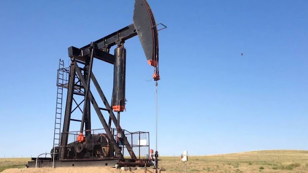
This is not a conventional Sucker Rod Pumping unit. This is special type of Pumping unit which is, Air balanced SRP. The air-balanced unit is a * rear mounted, class III lever system with Air Counter balance machine first built by Lufkin in early 1950’s.   (*Gear reducer and all accessories will be mounted at rear side of SRP). This machine uses the pitman to both push the walking beam up and pull the beam down to make a pumping cycle. The air-balanced unit uses an air tank fitted with an opened ended cylinder and piston to counterbalance the pumping unit. On the down stroke, air in the tank is further compressed thus storing energy in the compressed air.  Then on the up stroke the stored air energy is used to help lift part of the rod and fluid load. The piston uses piston rings to seal a pool of oil on top of the piston.  The pool of oil, in turn, seals the air from escaping from the tank and lubricates the piston/cylinder interface.    Click on icons to follow Us.